
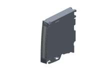
Siemens S7-1500, TM PTO4; 6ES7553-1AA00-0AB0
SIMATIC S7-1500, TM PTO 4 interface module for stepper drives 4 channels pulse train output PTO: 24 V, RS-422, 5 V, 2 DI, 1 DQ 24VDC per channel...
Cena na upit
| SIMATIC S7-1500, TM PTO 4 interface module for stepper drives 4 channels pulse train output PTO: 24 V, RS-422, 5 V, 2 DI, 1 DQ 24VDC per channel |
| General information | |
| Product type designation | TM PTO 4 |
| HW functional status | FS02 |
| Number of channels | 4; Axes |
| Product function | |
| ● I&M data | Yes; I&M0 to I&M3 |
| ● Isochronous mode | Yes |
| Engineering with | |
| ● STEP 7 TIA Portal configurable/integrated from version | STEP 7 V14 or higher |
| ● STEP 7 configurable/integrated from version | V5.5 SP3 with GSD file / - |
| ● PROFINET from GSD version/GSD revision | GSDML V2.32 |
| Installation type/mounting | |
| Rail mounting | Yes; S7-1500 mounting rail |
| Supply voltage | |
| Load voltage L+ | |
| ● Rated value (DC) | 24 V |
| ● permissible range, lower limit (DC) | 19.2 V |
| ● permissible range, upper limit (DC) | 28.8 V |
| ● Reverse polarity protection | Yes |
| Input current | |
| Current consumption, max. | 70 mA; without load |
| Power | |
| Power available from the backplane bus | 1.3 W |
| Power loss | |
| Power loss, typ. | 4 W |
| Address area | |
| Address space per module | |
| ● Inputs | 18 byte; Per channel |
| ● Outputs | 10 byte; Per channel |
| Digital inputs | |
| Number of digital inputs | 12; 3 per channel, of which 1 DIQ |
| Digital inputs, parameterizable | Yes |
| Input characteristic curve in accordance with IEC 61131, type 3 | Yes |
| Digital input functions, parameterizable | |
| ● Synchronization | Yes |
| ● Probe | Yes |
| ● Drive ready | Yes |
| Input voltage | |
| ● Type of input voltage | DC |
| ● Rated value (DC) | 24 V |
| ● for signal "0" | -5 ... +5 V |
| ● for signal "1" | +11 to +30V |
| ● permissible voltage at input, min. | -5 V |
| ● permissible voltage at input, max. | 30 V |
| Input current | |
| ● for signal "1", typ. | 2.5 mA |
| Input delay (for rated value of input voltage) | |
| for standard inputs | |
| — parameterizable | Yes; none / 0.05 / 0.1 / 0.4 / 0.8 / 1.6 / 3.2 / 12.8 / 20 ms |
| — at "0" to "1", min. | 4 µs; for parameterization "none" |
| — at "1" to "0", min. | 4 µs; for parameterization "none" |
| for technological functions | |
| — parameterizable | Yes |
| Cable length | |
| ● shielded, max. | 1 000 m |
| ● unshielded, max. | 600 m |
| Digital outputs | |
| Number of digital outputs | 12; 3 per channel, of which 1 DIQ |
| Current-sinking | Yes; For DQn.0 and DQn.1 push-pull outputs |
| Current-sourcing | Yes |
| Digital outputs, parameterizable | Yes |
| Short-circuit protection | Yes; electronic/thermal |
| ● Response threshold, typ. | 0.2 A for DQn.0 and DQn.1, 0.9 A for DIQn.2 |
| Controlling a digital input | Yes |
| Digital output functions, parameterizable | |
| ● PTO (pulse train output) signal interface | |
| — 24 V asymmetrical | Yes |
| — RS 422 symmetrical | Yes |
| — TTL (5 V) asymmetrical | Yes |
| ● PTO (pulse train output) signal type | |
| — Pulse and direction | Yes |
| — Count up, count down | Yes |
| — Incremental encoder (A, B phase shift) | Yes |
| — Incremental encoder (A, B phase shift, quadruple) | Yes |
| Switching capacity of the outputs | |
| ● with resistive load, max. | 0.1 A; 0.5 A for DIQn.2 |
| ● on lamp load, max. | 1 W; 5 W for DIQn.2 |
| Load resistance range | |
| ● lower limit | 240 Ω; 48 ohms for DIQn.2 |
| ● upper limit | 12 kΩ |
| Output voltage | |
| ● Type of output voltage | DC |
| ● for signal "1", min. | 23.2 V; L+ (-0.8 V), L+ (-1.3 V) for DIQn.2 |
| Output current | |
| ● for signal "1" rated value | 0.1 A; 0.5 A for DIQn.2 |
| ● for signal "1" permissible range, max. | 0.12 A; 0.6 A for DIQn.2 |
| ● for signal "1" minimum load current | 2 mA |
| ● for signal "0" residual current, max. | 0.5 mA |
| Output delay with resistive load | |
| ● "0" to "1", typ. | 1 µs; 28 µs for DIQn.2 |
| ● "1" to "0", typ. | 1 µs; 25 µs for DIQn.2 |
| Switching frequency | |
| ● with resistive load, max. | 1 kHz; For DIQn.2 |
| ● with inductive load, max. | 0.5 Hz; According to IEC 60947-5-1, DC-13, for DIQn.2 |
| ● on lamp load, max. | 10 Hz; For DIQn.2 |
| ● For signal interface 24 V asymmetrical | 200 kHz; With DQn.0 and DQn.1 |
| ● For signal interface RS 422 symmetrical | 1 MHz |
| ● For signal interface TTL (5 V) asymmetrical | 200 kHz |
| Cable length | |
| ● shielded, max. | 600 m; Cable length, RS 422 / TTL Siemens Type 6FX2001-5: 125 kHz, 320 meters shielded, max.; 250 kHz, 160 meters shielded, max.; 500 kHz, 60 meters shielded, max.; 1 MHz, 32 meters shielded, max. 24 V (DQn.x / DIQn.2): 10 kHz, 600 meters, shielded, max. 200 kHz, 50 meters shielded, max. |
| Isochronous mode | |
| Bus cycle time (TDP), min. | 250 µs; 375 µs if all 4 channels are used |
| Jitter, max. | 1 µs |
| Interrupts/diagnostics/status information | |
| Diagnostics function | Yes |
| Alarms | |
| ● Diagnostic alarm | Yes |
| Diagnoses | |
| ● Monitoring the supply voltage | Yes |
| ● Short-circuit | Yes; Thermal overload protection |
| ● Group error | Yes |
| Diagnostics indication LED | |
| ● RUN LED | Yes; green LED |
| ● ERROR LED | Yes; red LED |
| ● MAINT LED | Yes; Yellow LED |
| ● Monitoring of the supply voltage (PWR-LED) | Yes; green LED |
| ● Channel status display | Yes; green LED |
| ● for channel diagnostics | Yes; red LED |
| Potential separation | |
| Potential separation channels | |
| ● between the channels | No |
| ● between the channels and backplane bus | Yes |
| ● Between the channels and load voltage L+ | No |
| Isolation | |
| Isolation tested with | 707 V DC (type test) |
| Ambient conditions | |
| Ambient temperature during operation | |
| ● horizontal installation, min. | 0 °C |
| ● horizontal installation, max. | 60 °C; Observe derating |
| ● vertical installation, min. | 0 °C |
| ● vertical installation, max. | 40 °C; Observe derating |
| Altitude during operation relating to sea level | |
| ● Installation altitude above sea level, max. | 5 000 m; restrictions for installation altitudes > 2 000 m, see ET 200MP system manual |
| Decentralized operation | |
| to SIMATIC S7-300 | Yes; Via control and feedback interface |
| to SIMATIC S7-400 | Yes; Via control and feedback interface |
| to SIMATIC S7-1200 | Yes |
| to SIMATIC S7-1500 | Yes |
| to standard PROFINET controller | Yes; Via control and feedback interface |
| Dimensions | |
| Width | 35 mm |
| Height | 147 mm |
| Depth | 129 mm |
| Weights | |
| Weight, approx. | 300 g |
| last modified: | 3/2/2021 |
Slicni proizvodi:
Siemens S7-1500, TM PosInput 2; 6ES7551-1AB01-0AB0
SIMATIC S7-1500, TM PosInput 2 counter and position detection module for RS-422 incremental encoder or SSI absolute encoder, 2 channels, 2 DI, 2 DQ per channel
-

(Trenutno nema na stanju)
Cena na upit

Siemens S7-1500, TM Timer DIDQ 16x24V; 6ES7552-1AA00-0AB0
SIMATIC S7-1500, TM Timer DIDQ 16x 24 V time-controlled digital inputs and outputs max. 8 DI, 16 DQ of which max. 16 with time stamp, Count, PWM, oversampling
-
(Trenutno nema na stanju)
Cena na upit
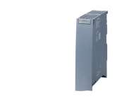
Siemens S7-1500, TM Count 2x24V; 6ES7550-1AA01-0AB0
SIMATIC S7-1500, TM count 2x 24 V counter module, 2 channels for 24 V incremental encoder or pulse encoder, 3 DI, 2 DQ per channel
-
(Trenutno nema na stanju)
Cena na upit
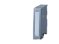
Siemens S7-1500, DI 32x24VDC/DQ 32x24VDC/0.3A BA; 6ES7523-1BP50-0AA0
SIMATIC S7-1500 digital input/output module, DI 32x24VDC BA SNK / SRC, 32 channels in groups of 16, input delay typ. 3.2 ms input type 3 (IEC 61131), sinking/sourcing
-
(Trenutno nema na stanju)
Cena na upit

Siemens SIMATIC S7-1500, Front connector in push-in design, 40-pole, for 35 mm wide modules; 6ES7592-1BM00-0XB0
SIMATIC S7-1500, Front connector in push-in design, 40-pole, for 35 mm wide modules incl. 4 potential bridges and cable ties
-
(Trenutno nema na stanju)
4.608,55